Students : Marcos Barrera, Tiemen van Rijswijk, Arjan Neelis, Syah Sury Alam, Marko Estrada Rodriguez
Github repository: https://github.com/syahsuri/Smr2-spraying-PIR-insulated-pipes-channels
The company
BRAGO Luchttechniek BV is responsible for the production, manufacture and distribution of air ducts. The production of these ducts involves the creation and folding of PIR plates, which are subsequently finalized with a polyester coating. The company specializes in making parametrically designed custom products for every industry or building. Notably, the entire production process is done by themselves with the exception of the polyester spraying.
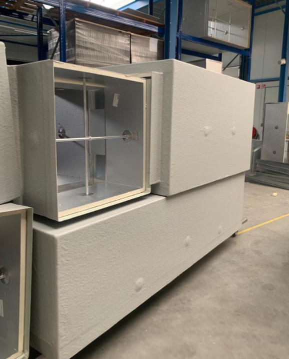

Figure 1: Photo of finished products Figure 2: Finished air duct
Original situation
Actually, the company executes the whole production process up to the point of spraying. Once the PIR plates are finished and folded, they are dispatched to an external supplier in order to spray the polyester along the duct. In this manner, once the supplier returns the products, the air ducts are fully finalized and prepared for delivery and installation at the client’s location.
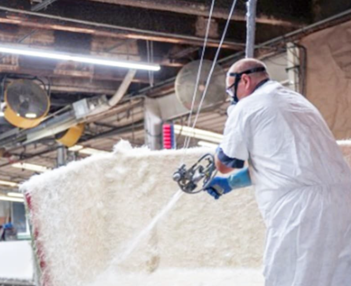
Figure 3: Actual spraying process
The problem
Originally, the company relied on a supplier for polyester spraying, but encountered certain disadvantages that required resolution. Mainly, they have to adapt to the other company’s necessities in terms of time and economic resources. Consequently, they decided to internalize this process.
However, the manual process also has some disadvantages. For example, there are no workers available to stay there the whole day performing that task, with the bad smell the process involves. In addition, they have some quality requirements that manually are not guaranteed.
Summarizing, this non-automated process presents a series of notable disadvantages:
- Inefficiency and reduced productivity: This manual process is inherently slower and more labor-intensive than the automated one.
- Inconsistency in quality: Human error is an inherent risk in non-automated processes. Inconsistent polyester application and bonding may lead to quality variations, negatively impacting the reputation of the company and customer satisfaction.
- Higher labor costs: The requirement for a significant labor force in manual operations contributes to higher labor costs, including wages, benefits, and training.
- Difficulty in process control and monitoring: Maintaining consistent quality and process control becomes more challenging without the precision and real-time monitoring capabilities of automation.
In conclusion, he company has contemplated automating this segment of the process to achieve greater efficiency in smart manufacturing. Eliminating this non automated task allows the company to use those employees for another task, without being aware of the spraying process. Furthermore, they will make an increase in quality technology and reliability, adapting to this new technological era.
The (automated) solution
The company wanted us to work on automating the spraying process. Through extensive brainstorming and collaborative efforts, we came up with the solution. The solution involves an automated system, incorporating a conveyor belt for moving the product into the robotic cell, a carrier tot transport the products and a turntable to access all sides of the product. The process is fully automated and conforms to safety rules thanks to sensors and safety procedures.
The entire process is controlled through a user interface (UI). In this manner, we have created a smart and automated system, avoiding the dirty human work and the economical and quality issues the process requires.
In this case, we will simulate the spraying with an UV lamp and glow-in-the-dark sheets that are going to be attached to each product, in order to make the result visible without spraying the actual product in the lab.
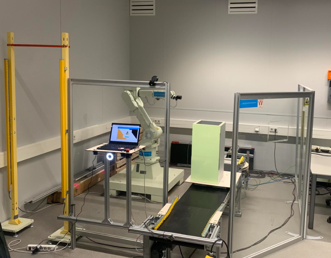
Figure 4: Our setup
For this process to be done, we had to work with these software, pneumatic and hand – made implementations:
RoboDK
The spraying pattern is different for every product. The robot trajectory thus needs to be computed for every product. Every product that needs to be processed has a CAD file (STL) available in a database.
The CAD file is first preprocessed in the STL-preprocesser. This orients all the products in the same way. By moving the origin into a suitable corner of the product and the XYZ in positive directions. It also computes some metadata to be used later in the process and generates a picture for the orientation of the product.
The product is then processed in RoboDK. This is a powerful offline simulator for robotics. The software provides useful features and enables offline programming.
The trajectory consists of two parts, the edge line and the surface pattern. The edge line is defined from the metadata and covers the edge of the product. The surface pattern then covers one side of the product. A wave is introduced into this pattern to ‘widen’ the path. After every side the product is, just like in real life on the turntable, turned.
The total program is then build up with homing, approach, etc. and converted into a Kawasaki program. This is then send to the robot and executed.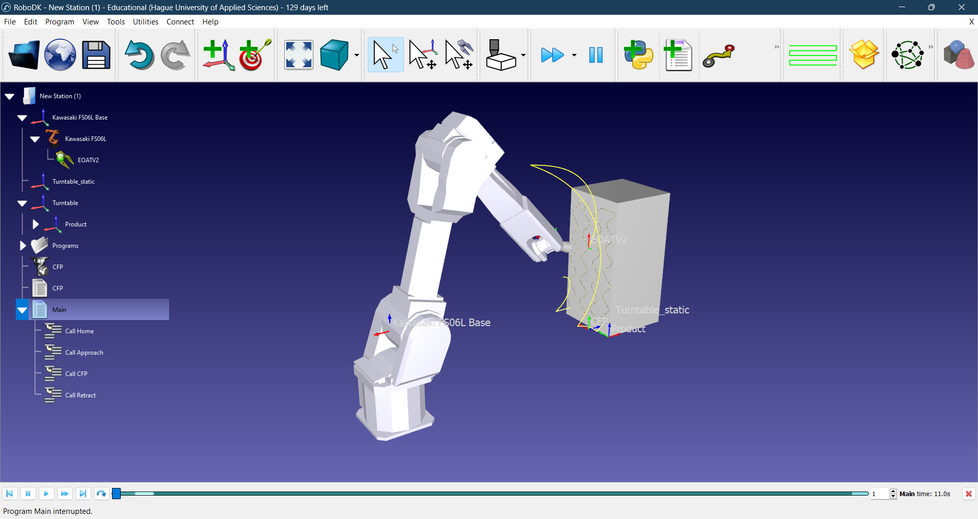
Figure 5: Photo of RoboDK programming
UI
Throughout the procedure, it is necessary to designate an employee to load in the product, including file selection and determining when to initiate or conclude the process. To facilitate these in an easy manner, the implementation of a User Interface (UI) for the company is essential. This interface has the control of the entire process, overseeing tasks such as determining the start, pausing or halting, and product selection.
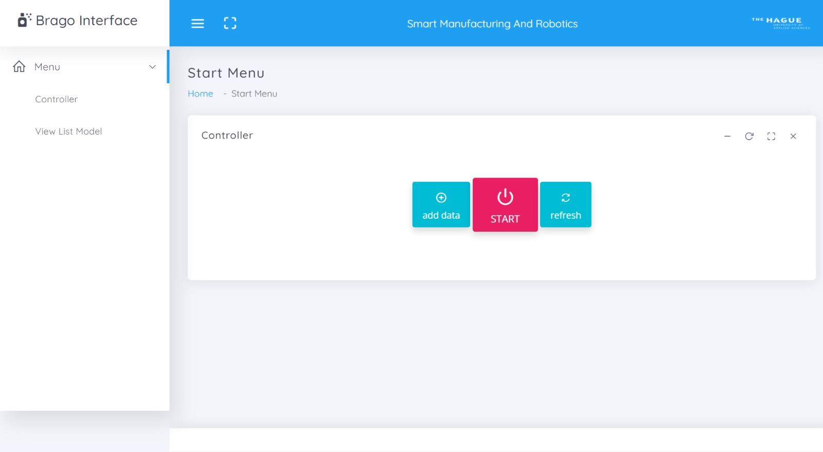
Figure 6: Photo of initial UI screen
Moreover, we have incorporated visual tools, such as a progress bar and process messages, designed in an accessible and comprehensible manner for the workers.
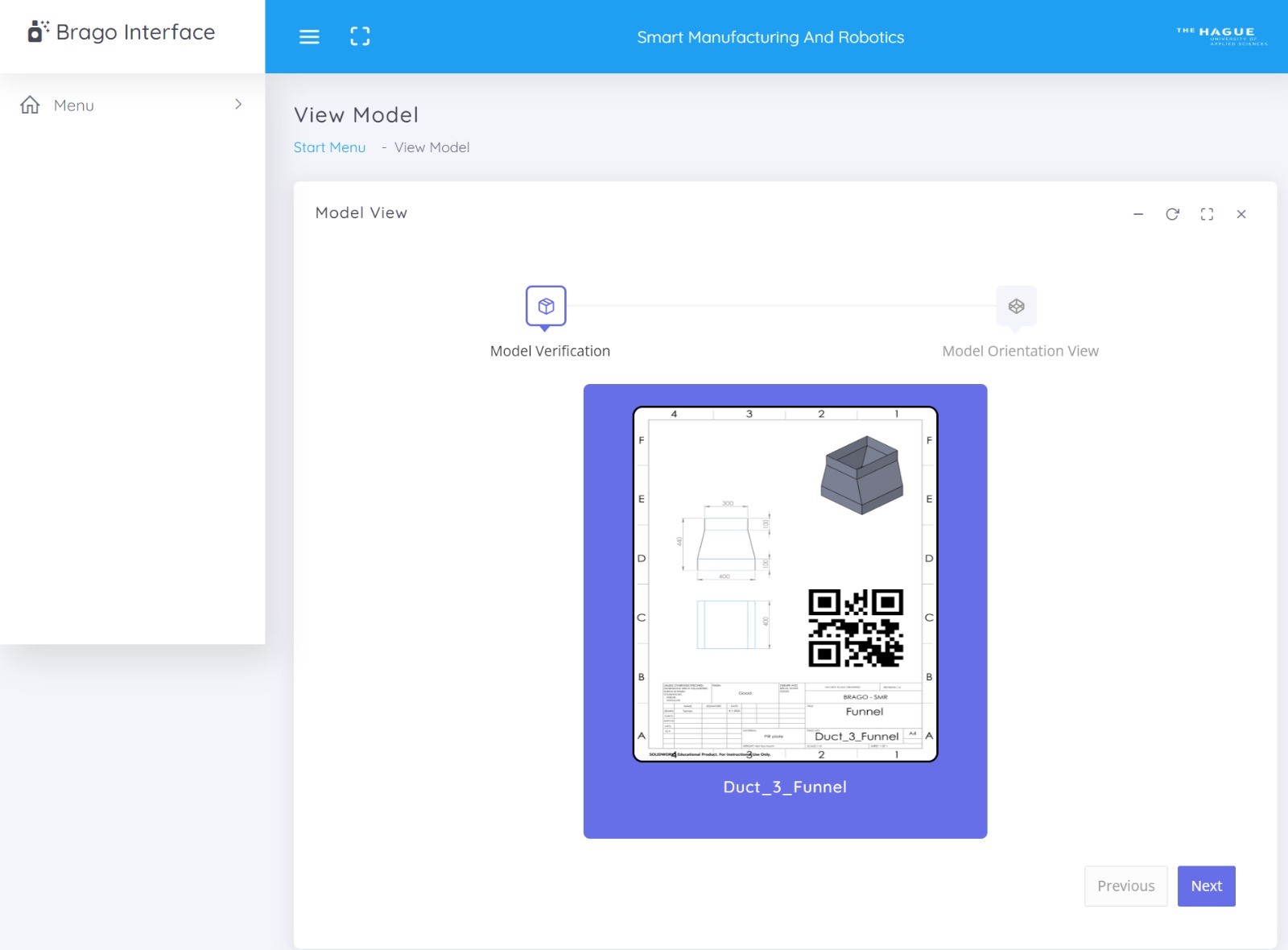
Figure 7: Photo of STL images selection screen
PLC
Programmable Logic Controller (PLC) is a specialized digital computer used in industrial automation and control systems to automate various electromechanical processes.
In particular, the conveyor belt, turntable, pusher, sensors implemented, etc needs to be controlled for activating and deactivating when it is necessary. For that reason, PLC is needed in our setup and plays a fundamental role.
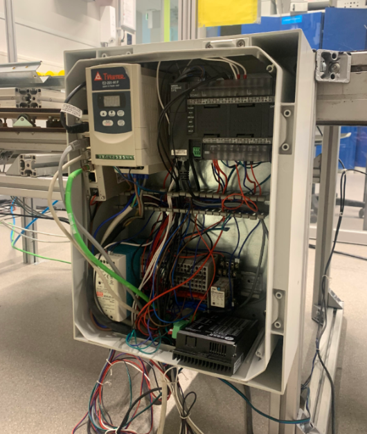
Figure 8: PLC setup
Camera Vision
We also used a robust camera vision software, with the purpose of recognising each QR code that is going to be attached to the product. Once the QR code is attached, the interface will know exactly which file in the database is linked to the product.
Communication
For interconnecting the whole process, we needed to have reliable communication between the camera vision part, the robot, the PLC and the interface. We decided to establish TCP communication between them and as each program is done with different software tools, we had to implement three servers in order to have a good connection. Our final communication setup visualised in the picture below:
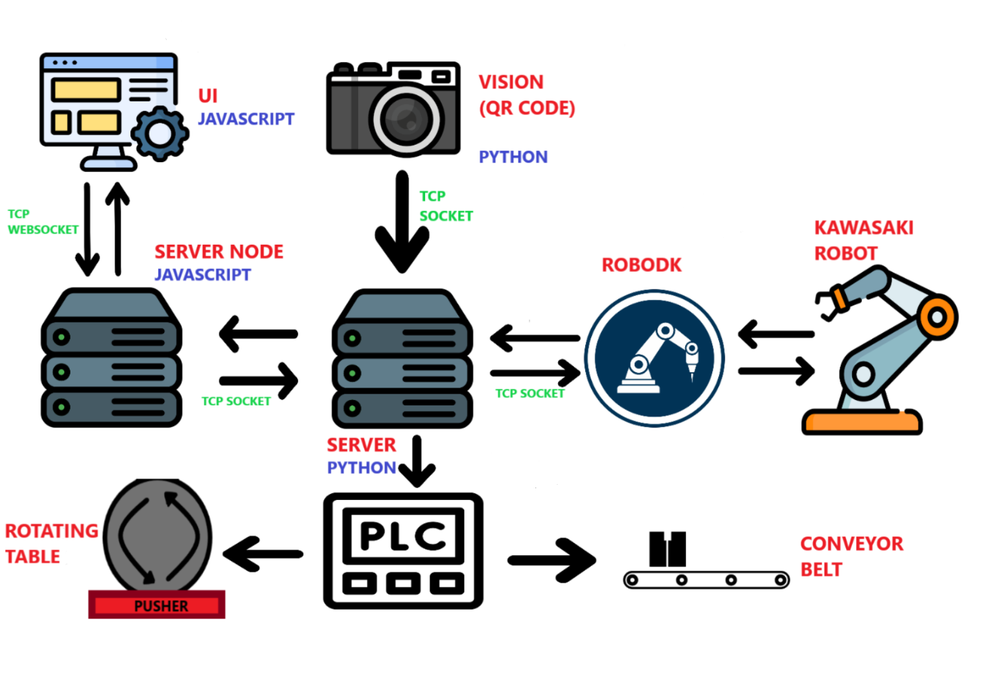
Figure 9: Visual sketch of our communication flow
End-of-arm tool
For this process, we made a simple end-of-arm tool (EoAT) in order to hold the light lamp. Actually, the lamp is mounted in 30º to avoid singularities. In reality, this EoAT should be changed to a more sophisticated one, holding the polyester gun and activating when needed.
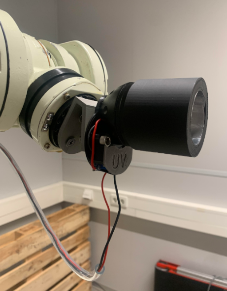
Figure 10: Lamp integrated as an EoAT
Our conclusion
In conclusion, the transition from a manual to an automated spraying process is a significant step toward achieving operational efficiency, quality enhancement, and adaptability to contemporary technological advancements. The integration of UV lamps and glow-in-the-dark sheets for simulation further demonstrates the result of an innovative and effective solution, achieving a really visual prototype for Brago. In this manner, this project allows easy note-taking and drawing conclusions, facilitating its incorporation and further development of the process.