Students: Cesar Pereira Horta , Rwan Fawzy
Introduction
RegalRexnord is a manufacturing company of motors, conveyer technologies, gearings, bearings and electronic components. Their dutch facility is located in Westland, South Holland.

Figure 1: Logo of RegalRexnord
Current situation
In the current situation, conveyer patterns are produced using a injection molding machine.
Next these patterns are assembled into conveyer belts by hand. By connecting the patterns with axes and seals they form a pattern for a conveyer belt. RegalRexnord looks for a way to automate the process of laying down the conveyer belt patterns.
Assignment
We got into contact with RegalRexnord and discussed the scope of their project assignment. Our goal was to build and program a Pick & Place line that is able to lay down conveyer belt patterns with their sizes ranging from six to to 21 inch, using two types of patterns from Rexnord. The requirement for this assignment was to pick and place one module per five seconds.
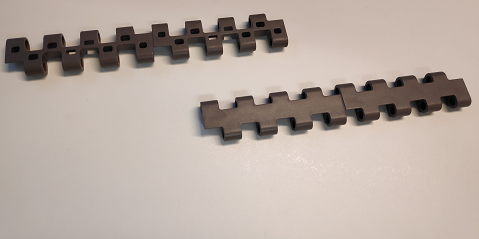
Figure 2: The two types of patterns used for the project

Figure 3: Conveyer belt sizes for this project
Our solution
Our project team built and programmed the production line that is able to lay down the patterns. It can be divided in parts to shed light on each subsystem of the production line:
Communication between subsystems
The production line is controlled by the server running on Python on a laptop. This program sends orders to the other parts of the production line. This being:
- The PLC that controls the conveyer belt for supplying patterns into the production line as well as the HMI for entering the desireable conveyer belt to be placed down.
- The Kawasaki robot.
To make communication work we implemented TCP communication between these subsystems and Python allowing for everything listen, send and receive messages and thus work together.
Supplying patterns into the work area
To make sure the robot gets conveyer patterns delivered to it, we used a conveyer belt to carry conveyer patterns to the robot. This conveyer belt is controlled by the PLC, which in turn is controlled by Python. This allows us to program the conveyer belt setting in Python and determine how much it needs to move in order to supply patterns for the robot.
Gripper design
In order to be able to pick up the pattern arriving on the conveyer belt we designed a gripper to be able to pick and place the pattern. We decided to have the robot pick up the patterns at the small holes on the sides of the patterns ‘teeth’ and designed our grippers to insert in these holes.
Because picking the patterns at the small holes is a high precision task, we used 3D-printing to create the gripper parts. We designed the gripper parts so these could be fixated on a pneumatic Schunk gripper. This pneumatic gripper was in turn controlled by the Kawasaki computer.
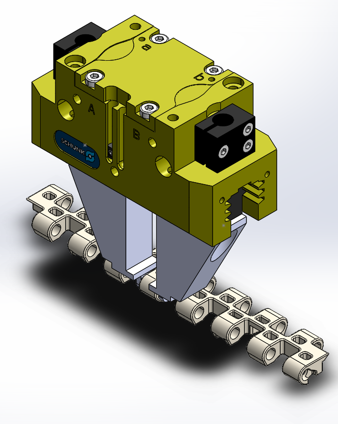
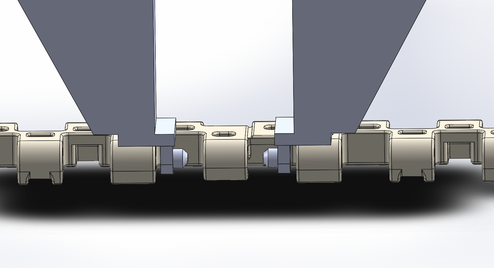
Figure 4 and 5: Gripper design in Solidworks to pick up both types of patterns
Later on we made adjustments to our gripper in order to pick up the frailer second pattern type. This second version of the gripper picks up patterns at one tooth instead of the two teeth shown in this article. This way we were able to pick up both module types.
Pattern placing algorithm
In order to place down patterns to create conveyer patterns we programmed a algorithm sequence. To do this we programmed the starting positions of the first conveyer patterns into the robot.
When the robot starts to place down patterns it will first place the patterns down on these positions. Then it resumes and will enter a loop.
This loop and algorithm works incrementary. This means that everytime the robot finishes placing down a row of patterns, a counter programmed in the robot will be incremented and this counter increases the distance the robot moves away from the original positions of the module patterns.
This means that everytime a row is finished, it will move further away to place a row next to the previous row, allowing the robot to lay down the conveyer belt pattern with great precision. Figure 4 illustrates how the incrementary algorithm looks like.
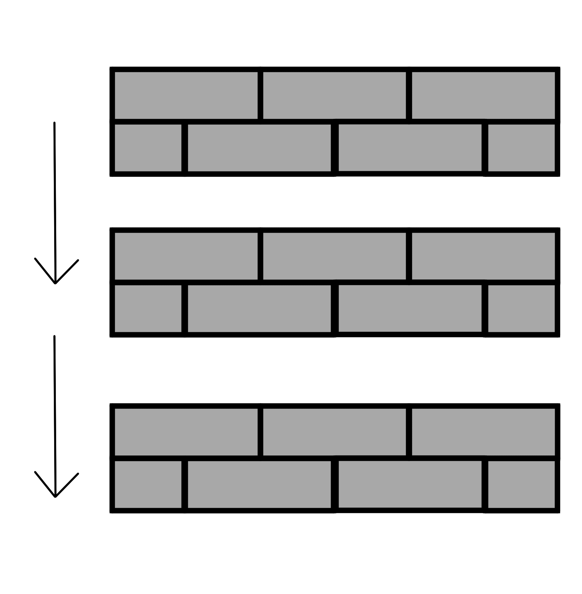
Figure 6: Illustration of how the incrementary algorithm moves the current row next to the previous row.
Quality Control with vision
In order to have the computer determine whether a conveyer pattern is placed correctly or not, we implemented vision.
The vision code involves a camera stationed in the working area of the robot, and it activates only when it determines there are patterns underneath it. It is used at the end of placing a conveyer pattern to determine the quality of the placed conveyer belt.
The vision code tests the conveyer belt based on its size, length and on any open spots due to missing patterns.
First vision will check the length and size of the biggest object visible to the camera, which is the conveyer belt. Based on the desireable length and size of the order vision will determine the quality of the conveyer belt. If the length and size are not equal to the desireable size and length it will reject the conveyer belt.
If the size and length check are passed it will then start a check for missing patterns in the conveyer belt. Vision will open up a additional screen to showcase only the ‘inside’ of the conveyer belt. If there are missing patterns vision will reject the belt. Only if both tests are passed vision will deem the conveyer belt as succesfull.
Examples of this are shown in Figure 7 to Figure 9.
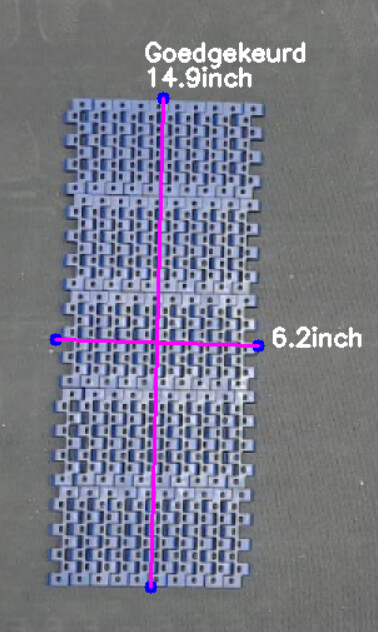
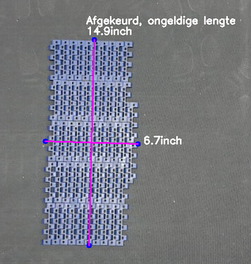
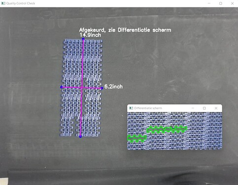
Figure 7 to 9: Quality Control with vision. From top to bottom:
– Succesful
– Failure due to too many or too little pattern(s)
– Failure due to a pattern or patterns missing in the conveyer belt
Conclusion
During the project we had some setbacks. Some systems like the conveyer belt and the Kawasaki robot proved to be older and were not 100% reliable during our tests.
Despite this, we managed to work around these setbacks to make our production line work. We showed our production line to our client from RegalRexnord and he was satisfied.